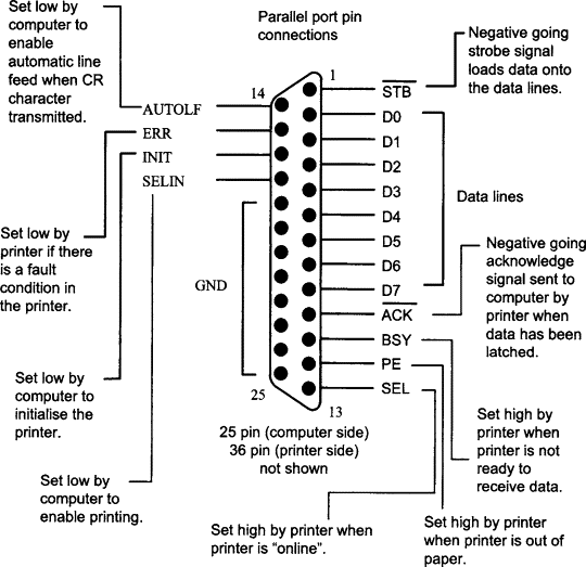

Until proven otherwise, I will assume that the parallel port conforms to the pinout shown in the above diagram. It is highly unlikely that it does not.
Writing software to put data on the 8 data pins is trivial, as shown by code in the bootrom. You simply write to physical address 0x6f00003c. Doing things with the other pins is another matter.
A status register at 0x6f00003d yields:
#define PS_READY    0x80    /* -BUSY: printer not busy */
#define PS_NOTACK   0x40    /* -ACK: ACK state */
#define PS_NOPAPER  0x20    /* +PE: printer out of paper */
#define PS_SELECT   0x10    /* +SLCT: printer is selected */
#define PS_NOERROR  0x08    /* -ERROR: printer error condition */
A control register at 0x6f00003e gives access to these signals:
#define PC_SELECT   0x08    /* +SLCT IN: select printer */
#define PC_INIT     0x04    /* -INIT: init printer */
#define PC_LINEFEED 0x02    /* +AUTO FD XT: set auto linefeed */
#define PC_STROBE   0x01    /* +STROBE: strobe data */
So in addition to the 8 data signals, we have 5 status and 4 control signals.
The data signals are unidirectional (output only). It is supposed to be a printer after all.
Tom's Computer Info / [email protected]